


SPI Graphic Lcd Library
The mikroBasic PRO for 8051 provides a library for operating Graphic Lcd 128x64 (with commonly used Samsung KS108/KS107 controller) via SPI interface.
For creating a custom set of Glcd images use Glcd Bitmap Editor Tool.
Notes:
- The library uses the SPI module for communication. User must initialize SPI module before using the SPI Graphic Lcd Library.
- This Library is designed to work with the mikroElektronika's Serial Lcd/Glcd Adapter Board pinout, see schematic at the bottom of this page for details.
External dependencies of SPI Graphic LcdLibrary
The implementation of SPI Graphic Lcd Library routines is based on Port Expander Library routines.
External dependencies are the same as Port Expander Library external dependencies.
Library Routines
Basic routines:
- SPI_Glcd_Init
- SPI_Glcd_Set_Side
- SPI_Glcd_Set_Page
- SPI_Glcd_Set_X
- SPI_Glcd_Read_Data
- SPI_Glcd_Write_Data
Advanced routines:
- SPI_Glcd_Fill
- SPI_Glcd_Dot
- SPI_Glcd_Line
- SPI_Glcd_V_Line
- SPI_Glcd_H_Line
- SPI_Glcd_Rectangle
- SPI_Glcd_Box
- SPI_Glcd_Circle
- SPI_Glcd_Set_Font
- SPI_Glcd_Write_Char
- SPI_Glcd_Write_Text
- SPI_Glcd_Image
SPI_Glcd_Init
| Prototype |
sub procedure SPI_Glcd_Init(dim DeviceAddress as byte) |
|---|---|
| Returns |
Nothing. |
| Description |
Initializes the Glcd module via SPI interface. Parameters :
|
| Requires |
The SPI module needs to be initialized. See SPIx_Init and SPIx_Init_Advanced routines. |
| Example |
' port expander pinout definition
dim SPExpanderRST as sbit at P1_0_bit
    SPExpanderCS as sbit at P1_1_bit
...
SPI1_Init_Advanced(MASTER_OSC_DIV4 or CLK_IDLE_LOW or IDLE_2_ACTIVE or DATA_ORDER_MSB)
SPI_Glcd_Init(0)
|
SPI_Glcd_Set_Side
| Prototype |
sub procedure SPI_Glcd_Set_Side(dim x_pos as byte) |
|---|---|
| Returns |
Nothing. |
| Description |
Selects Glcd side. Refer to the Glcd datasheet for detail explanation. Parameters :
The parameter Note: For side, x axis and page layout explanation see schematic at the bottom of this page. |
| Requires |
Glcd needs to be initialized for SPI communication, see SPI_Glcd_Init routines. |
| Example |
The following two lines are equivalent, and both of them select the left side of Glcd: SPI_Glcd_Set_Side(0) SPI_Glcd_Set_Side(10) |
SPI_Glcd_Set_Page
| Prototype |
sub procedure SPI_Glcd_Set_Page(dim page as byte) |
|---|---|
| Returns |
Nothing. |
| Description |
Selects page of Glcd. Parameters :
Note: For side, x axis and page layout explanation see schematic at the bottom of this page. |
| Requires |
Glcd needs to be initialized for SPI communication, see SPI_Glcd_Init routines. |
| Example |
SPI_Glcd_Set_Page(5) |
SPI_Glcd_Set_X
| Prototype |
sub procedure SPI_Glcd_Set_X(dim x_pos as byte) |
|---|---|
| Returns |
Nothing. |
| Description |
Sets x-axis position to Parameters :
Note: For side, x axis and page layout explanation see schematic at the bottom of this page. |
| Requires |
Glcd needs to be initialized for SPI communication, see SPI_Glcd_Init routines. |
| Example |
SPI_Glcd_Set_X(25) |
SPI_Glcd_Read_Data
| Prototype |
sub function SPI_Glcd_Read_Data() as byte |
|---|---|
| Returns |
One byte from Glcd memory. |
| Description |
Reads data from the current location of Glcd memory and moves to the next location. |
| Requires |
Glcd needs to be initialized for SPI communication, see SPI_Glcd_Init routines. Glcd side, x-axis position and page should be set first. See the functions SPI_Glcd_Set_Side, SPI_Glcd_Set_X, and SPI_Glcd_Set_Page. |
| Example |
dim data as byte ... data = SPI_Glcd_Read_Data() |
SPI_Glcd_Write_Data
| Prototype |
sub procedure SPI_Glcd_Write_Data(dim Ddata as byte) |
|---|---|
| Returns |
Nothing. |
| Description |
Writes one byte to the current location in Glcd memory and moves to the next location. Parameters :
|
| Requires |
Glcd needs to be initialized for SPI communication, see SPI_Glcd_Init routines. Glcd side, x-axis position and page should be set first. See the functions SPI_Glcd_Set_Side, SPI_Glcd_Set_X, and SPI_Glcd_Set_Page. |
| Example |
dim ddata as byte ... SPI_Glcd_Write_Data(ddata) |
SPI_Glcd_Fill
| Prototype |
sub procedure SPI_Glcd_Fill(dim pattern as byte) |
|---|---|
| Returns |
Nothing. |
| Description |
Fills Glcd memory with byte Parameters :
To clear the Glcd screen, use To fill the screen completely, use |
| Requires |
Glcd needs to be initialized for SPI communication, see SPI_Glcd_Init routines. |
| Example |
' Clear screen SPI_Glcd_Fill(0) |
SPI_Glcd_Dot
| Prototype |
sub procedure SPI_Glcd_Dot(dim x_pos as byte, dim y_pos as byte, dim color as byte) |
|---|---|
| Returns |
Nothing. |
| Description |
Draws a dot on Glcd at coordinates ( Parameters :
The parameter Note: For x and y axis layout explanation see schematic at the bottom of this page. |
| Requires |
Glcd needs to be initialized for SPI communication, see SPI_Glcd_Init routines. |
| Example |
' Invert the dot in the upper left corner SPI_Glcd_Dot(0, 0, 2) |
SPI_Glcd_Line
| Prototype |
sub procedure SPI_Glcd_Line(dim x_start as integer, dim y_start as integer, dim x_end as integer, dim y_end as integer, dim color as byte) |
|---|---|
| Returns |
Nothing. |
| Description |
Draws a line on Glcd. Parameters :
Parameter |
| Requires |
Glcd needs to be initialized for SPI communication, see SPI_Glcd_Init routines. |
| Example |
' Draw a line between dots (0,0) and (20,30) SPI_Glcd_Line(0, 0, 20, 30, 1) |
SPI_Glcd_V_Line
| Prototype |
sub procedure SPI_Glcd_V_Line(dim y_start as byte, dim y_end as byte, dim x_pos as byte, dim color as byte) |
|---|---|
| Returns |
Nothing. |
| Description |
Draws a vertical line on Glcd. Parameters :
Parameter |
| Requires |
Glcd needs to be initialized for SPI communication, see SPI_Glcd_Init routines. |
| Example |
' Draw a vertical line between dots (10,5) and (10,25) SPI_Glcd_V_Line(5, 25, 10, 1) |
SPI_Glcd_H_Line
| Prototype |
sub procedure SPI_Glcd_V_Line(dim x_start as byte, dim x_end as byte, dim y_pos as byte, dim color as byte) |
|---|---|
| Returns |
Nothing. |
| Description |
Draws a horizontal line on Glcd. Parameters :
The parameter |
| Requires |
Glcd needs to be initialized for SPI communication, see SPI_Glcd_Init routines. |
| Example |
' Draw a horizontal line between dots (10,20) and (50,20) SPI_Glcd_H_Line(10, 50, 20, 1) |
SPI_Glcd_Rectangle
| Prototype |
sub procedure SPI_Glcd_Rectangle(dim x_upper_left as byte, dim y_upper_left as byte, dim x_bottom_right as byte, dim y_bottom_right as byte, dim color as byte) |
|---|---|
| Returns |
Nothing. |
| Description |
Draws a rectangle on Glcd. Parameters :
The parameter |
| Requires |
Glcd needs to be initialized for SPI communication, see SPI_Glcd_Init routines. |
| Example |
' Draw a rectangle between dots (5,5) and (40,40) SPI_Glcd_Rectangle(5, 5, 40, 40, 1) |
SPI_Glcd_Box
| Prototype |
sub procedure SPI_Glcd_Box(dim x_upper_left as byte, dim y_upper_left as byte, dim x_bottom_right as byte, dim y_bottom_right as byte, dim color as byte) |
|---|---|
| Returns |
Nothing. |
| Description |
Draws a box on Glcd. Parameters :
The parameter |
| Requires |
Glcd needs to be initialized for SPI communication, see SPI_Glcd_Init routines. |
| Example |
' Draw a box between dots (5,15) and (20,40) SPI_Glcd_Box(5, 15, 20, 40, 1) |
SPI_Glcd_Circle
| Prototype |
sub procedure SPI_Glcd_Circle(dim x_center as integer, dim y_center as integer, dim radius as integer, dim color as byte) |
|---|---|
| Returns |
Nothing. |
| Description |
Draws a circle on Glcd. Parameters :
The parameter |
| Requires |
Glcd needs to be initialized for SPI communication, see SPI_Glcd_Init routine. |
| Example |
' Draw a circle with center in (50,50) and radius=10 SPI_Glcd_Circle(50, 50, 10, 1) |
SPI_Glcd_Set_Font
| Prototype |
sub procedure SPI_Glcd_Set_Font(dim const activeFont as ^byte, dim aFontWidth as byte, dim aFontHeight as byte, dim aFontOffs as word) |
|---|---|
| Returns |
Nothing. |
| Description |
Sets font that will be used with SPI_Glcd_Write_Char and SPI_Glcd_Write_Text routines. Parameters :
The user can use fonts given in the file “__Lib_Glcd_fonts.mbas” file located in the Uses folder or create his own fonts. |
| Requires |
Glcd needs to be initialized for SPI communication, see SPI_Glcd_Init routines. |
| Example |
' Use the custom 5x7 font "myfont" which starts with space (32): SPI_Glcd_Set_Font(myfont, 5, 7, 32) |
SPI_Glcd_Write_Char
| Prototype |
sub procedure SPI_Glcd_Write_Char(dim chr1 as byte, dim x_pos as byte, dim page_num as byte, dim color as byte) |
|---|---|
| Returns |
Nothing. |
| Description |
Prints character on Glcd. Parameters :
The parameter Note: For x axis and page layout explanation see schematic at the bottom of this page. |
| Requires |
Glcd needs to be initialized for SPI communication, see SPI_Glcd_Init routines. Use the SPI_Glcd_Set_Font to specify the font for display; if no font is specified, then the default 5x8 font supplied with the library will be used. |
| Example |
' Write character 'C' on the position 10 inside the page 2:
SPI_Glcd_Write_Char("C", 10, 2, 1)
|
SPI_Glcd_Write_Text
| Prototype |
sub procedure SPI_Glcd_Write_Text(dim byref text as string[20], dim x_pos as byte, dim page_numb as byte, dim color as byte) |
|---|---|
| Returns |
Nothing. |
| Description |
Prints text on Glcd. Parameters :
The parameter Note: For x axis and page layout explanation see schematic at the bottom of this page. |
| Requires |
Glcd needs to be initialized for SPI communication, see SPI_Glcd_Init routines. Use the SPI_Glcd_Set_Font to specify the font for display; if no font is specified, then the default 5x8 font supplied with the library will be used. |
| Example |
' Write text "Hello world!" on the position 10 inside the page 2:
SPI_Glcd_Write_Text("Hello world!", 10, 2, 1)
|
SPI_Glcd_Image
| Prototype |
sub procedure SPI_Glcd_Image(dim const image as ^byte) |
|---|---|
| Returns |
Nothing. |
| Description |
Displays bitmap on Glcd. Parameters :
Use the mikroBasic’s integrated Glcd Bitmap Editor (menu option Tools › Glcd Bitmap Editor) to convert image to a constant array suitable for displaying on Glcd. |
| Requires |
Glcd needs to be initialized for SPI communication, see SPI_Glcd_Init routines. |
| Example |
' Draw image my_image on Glcd SPI_Glcd_Image(my_image) |
Library Example
The example demonstrates how to communicate to KS0108 Glcd via the SPI module, using serial to parallel convertor MCP23S17.
program SPI_Glcd

' Port Expander module connections
dim SPExpanderRST as sbit at P1_0_bit
dim SPExpanderCS  as sbit at P1_1_bit
' End Port Expander module connections

dim someText as char[20]
    counter as byte

#DEFINE COMPLETE_EXAMPLE                        ' Uncomment this line for complete example

sub procedure delay2S
  Delay_ms(2000)
end sub

main:
  ' If Port Expander Library uses SPI1 module
  SPI1_Init_Advanced(_SPI_FCY_DIV4 or _SPI_CLK_IDLE_LO or _SPI_CLK_IDLE_2_ACTIVE) ' Initialize SPI module used with PortExpander

  ' If Port Expander Library uses SPI2 module
  ' SPI2_Init()                                 ' Initialize SPI module used with PortExpander

  SPI_Glcd_Init(0)                             ' Initialize Glcd via SPI
  SPI_Glcd_Fill(0x00)                          ' Clear Glcd

  while (TRUE)
    #IFDEF COMPLETE_EXAMPLE
    SPI_Glcd_Image(@truck_bmp)                  ' Draw image
    Delay2s() Delay2s()

    SPI_Glcd_Fill(0x00)                         ' Clear Glcd
    Delay2s

    SPI_Glcd_Box(62,40,124,56,1)                ' Draw box
    SPI_Glcd_Rectangle(5,5,84,35,1)             ' Draw rectangle
    SPI_Glcd_Line(0, 63, 127, 0,1)              ' Draw line
    Delay2s()
    #ENDIF
    counter = 5
    while (counter < 60)   ' Draw horizontal and vertical line
      Delay_ms(250)
      SPI_Glcd_V_Line(2, 54, counter, 1)
      SPI_Glcd_H_Line(2, 120, counter, 1)
      counter = counter + 5
    wend
    Delay2s()

    SPI_Glcd_Fill(0x00)
    #IFDEF COMPLETE_EXAMPLE                    ' Clear Glcd
    SPI_Glcd_Set_Font(@Character8x7, 8, 8, 32)  ' Choose font Character8x7
    SPI_Glcd_Write_Text("mikroE", 5, 7, 2)      ' Write string

    for counter = 1 to 10                       ' Draw circles
      SPI_Glcd_Circle(63,32, 3*counter, 1)
    next counter
    Delay2s()

    SPI_Glcd_Box(12,20, 70,63, 2)               ' Draw box
    Delay2s()

    SPI_Glcd_Fill(0xFF)                         ' Fill Glcd

    SPI_Glcd_Set_Font(@Character8x7, 8, 7, 32)  ' Change font
    someText = "8x7 Font"
    SPI_Glcd_Write_Text(someText, 5, 1, 2)      ' Write string
    Delay2s()

    SPI_Glcd_Set_Font(@System3x5, 3, 5, 32)     ' Change font
    someText = "3X5 CAPITALS ONLY"
    SPI_Glcd_Write_Text(someText, 5, 3, 2)      ' Write string
    Delay2s()

    SPI_Glcd_Set_Font(@font5x7, 5, 7, 32)       ' Change font
    someText = "5x7 Font"
    SPI_Glcd_Write_Text(someText, 5, 5, 2)      ' Write string
    Delay2s()

    SPI_Glcd_Set_Font(@FontSystem5x7_v2, 5, 7, 32) ' Change font
    someText = "5x7 Font (v2)"
    SPI_Glcd_Write_Text(someText, 5, 7, 2)         ' Write string
    Delay2s()
    #ENDIF
wend
end.
HW Connection
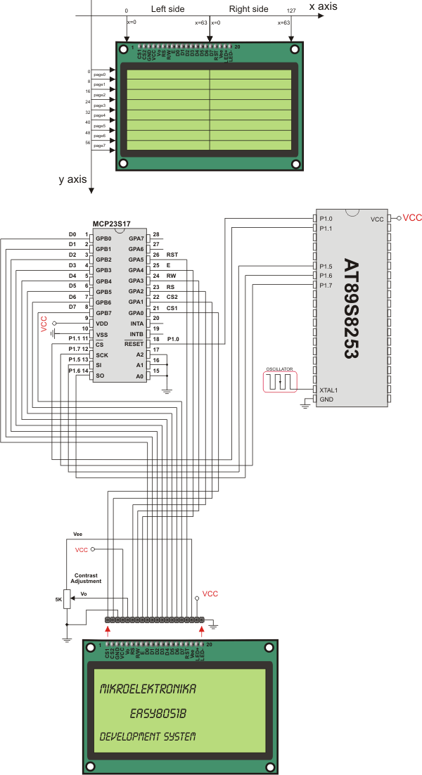
SPI Glcd HW connection
What do you think about this topic ? Send us feedback!
Find them on
