PWM Library
CCP module is available with a number of PIC MCUs. mikroPascal PRO for PIC provides library which simplifies using PWM HW Module.
 Important :
- Some MCUs have multiple CCP modules. In order to use the desired CCP library routine, simply change the number
1in the prototype with the appropriate module number, i.e.PWM2_Start();. - All PWM modules use Timer2 for its operation, so you can not set different frequencies for different PWM modules.
Library Routines
PWM1_Init
| Prototype |
procedure PWM1_Init(const freq : longint); |
|---|---|
| Returns |
Nothing. |
| Description |
Initializes the PWM module with duty ratio 0. Parameter This routine needs to be called before using other functions from PWM Library. |
| Requires |
MCU must have CCP module.  Note :
Calculation of the PWM frequency value is carried out by the compiler, as it would produce a relatively large code if performed on the libary level. Note :
Calculation of the PWM frequency value is carried out by the compiler, as it would produce a relatively large code if performed on the libary level. Therefore, compiler needs to know the value of the parameter in the compile time. That is why this parameter needs to be a constant, and not a variable. |
| Example |
Initialize PWM module at 5KHz: PWM1_Init(5000); |
PWM1_Set_Duty
| Prototype |
procedure PWM1_Set_Duty(duty_ratio : byte); |
|---|---|
| Returns |
Nothing. |
| Description |
Sets PWM duty ratio. Parameter |
| Requires |
MCU must have CCP module. PWM1_Init must be called before using this routine. |
| Example |
Set duty ratio to 75%: PWM1_Set_Duty(192); |
PWM1_Start
| Prototype |
procedure PWM1_Start(); |
|---|---|
| Returns |
Nothing. |
| Description |
Starts PWM. |
| Requires |
MCU must have CCP module. PWM1_Init must be called before using this routine. |
| Example |
PWM1_Start(); |
PWM1_Stop
| Prototype |
procedure PWM1_Stop(); |
|---|---|
| Returns |
Nothing. |
| Description |
Stops PWM. |
| Requires |
MCU must have CCP module. PWM1_Init must be called before using this routine. PWM1_Start should be called before using this routine, otherwise it will have no effect as the PWM module is not running. |
| Example |
PWM1_Stop(); |
Library Example
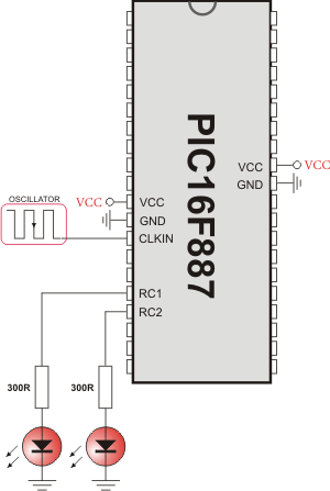
The example changes PWM duty ratio on RC1 and RC2 pins continually. If LED is connected to these pins, you can observe the gradual change of emitted light.
program PWM_Test;

var current_duty, current_duty1, old_duty, old_duty1 : byte;

procedure InitMain();
  begin
    ANSEL  := 0;                        // Configure AN pins as digital I/O
    ANSELH := 0;

    PORTA := 255;
    TRISA := 255;                       // configure PORTA pins as input
    PORTB := 0;                         // set PORTB to 0
    TRISB := 0;                         // designate PORTB pins as output
    PORTC := 0;                         // set PORTC to 0
    TRISC := 0;                         // designate PORTC pins as output
    PWM1_Init(5000);                    // Initialize PWM1 module at 5KHz
    PWM2_Init(5000);                    // Initialize PWM2 module at 5KHz
  end;

begin
  InitMain();
  current_duty  := 16;                  // initial value for current_duty
  current_duty1 := 16;                  // initial value for current_duty1

  PWM1_Start();                         // start PWM1
  PWM2_Start();                         // start PWM2
  PWM1_Set_Duty(current_duty);          // Set current duty for PWM1
  PWM2_Set_Duty(current_duty1);         // Set current duty for PWM2

  while (TRUE) do                       // endless loop
    begin
      if (RA0_bit <> 0) then            // button on RA0 pressed
        begin
          Delay_ms(40);
          Inc(current_duty);            // increment current_duty
          PWM1_Set_Duty(current_duty);
        end;

      if (RA1_bit <> 0) then            // button on RA1 pressed
        begin
          Delay_ms(40);
          Dec(current_duty);            // decrement current_duty
          PWM1_Set_Duty(current_duty);
        end;

      if (RA2_bit <> 0) then            // button on RA2 pressed
        begin
          Delay_ms(40);
          Inc(current_duty1);           // increment current_duty1
          PWM2_Set_Duty(current_duty1);
        end;

      if (RA3_bit <> 0) then            // button on RA3 pressed
        begin
          Delay_ms(40);
          Dec(current_duty1);           // decrement current_duty1
          PWM2_Set_Duty(current_duty1);
        end;

      Delay_ms(5);                      // slow down change pace a little
    end;
end.
HW Connection

PWM demonstration
What do you think about this topic ? Send us feedback!


