ADC Library
ADC (Analog to Digital Converter) module is available with a number of AVR MCU modules. ADC is an electronic circuit that converts continuous signals to discrete digital numbers. ADC Library provides you a comfortable work with the module.
Library Routines
ADC_Init
| Prototype |
procedure ADC_Init(); // for XMEGA family of MCUsprocedure ADCx_Init(); |
|---|---|
| Returns |
Nothing. |
| Description |
Initializes internal ADC module to work with XTAL frequency prescaled by 128. Clock determines the time period necessary for performing A/D conversion. For XMEGA family of MCUs change the X in the routine prototype with A or B. |
| Requires |
|
| Example |
ADC_Init(); // Initialize ADC module with default settings ADCA_Init(); // Initialize ADC module with default settings |
ADCx_Init_Advanced
| Prototype |
procedure ADCx_Init_Advanced(AdcMode, Reference : byte); |
||||||||||||||||||
|---|---|---|---|---|---|---|---|---|---|---|---|---|---|---|---|---|---|---|---|
| Returns |
Nothing. |
||||||||||||||||||
| Description |
Parameters
|
||||||||||||||||||
| Requires |
|
||||||||||||||||||
| Example |
ADCA_Init_Advanced(_ADC_12bit, _ADC_INTERNAL_REF_1V); // Initialize ADC module with 12bit resolution and internal voltage reference of 1V |
||||||||||||||||||
ADC_Get_Sample
| Prototype |
function ADC_Get_Sample(channel : byte) : word; // for XMEGA family of MCUsfunction ADCx_Get_Sample(channel : byte) : word; |
|---|---|
| Returns |
10-bit or 12-bit unsigned value (MCU dependent) from the specified |
| Description |
Routine acquires analog value from the specified channel. Parameter For XMEGA family of MCUs change the X in the routine prototype with A or B. |
| Requires |
|
| Example |
var adc_value : word ... ADC_Init(); // Initialize ADC module with default settings adc_value := ADC_Get_Sample(2); // Acquire analog value from channel 2 |
ADC_Read
| Prototype |
function ADC_Read(channel : byte) : word; // for XMEGA family of MCUsfunction ADCx_Read(channel : byte) : word; |
|---|---|
| Returns |
10-bit or 12-bit unsigned value (MCU dependent) from the specified |
| Description |
Routine initializes internal ADC module and acquires analog value from the specified Parameter For XMEGA family of MCUs change the X in the routine prototype with A or B. |
| Requires |
Nothing. |
| Example |
var tmp : word; ... tmp := ADC_Read(2); // initialize ADC module and acquire analog value from ADC module channel 2 |
ADC_Set_Active
| Prototype |
procedure ADC_Set_Active(adc_gs : ^TADC_Get_Sample); |
|---|---|
| Description |
Sets active ADC module. |
| Parameters |
Parameters :
|
| Returns |
Nothing. |
| Requires |
Routine is available only for MCUs with multiple ADC modules. Used ADC module must be initialized before using this routine. See ADC_Init and ADCx_Init_Advanced routines. |
| Example |
// Activate ADC2 module ADC_Set_Active(@ADC2_Get_Sample); |
| Notes |
None. |
Library Example
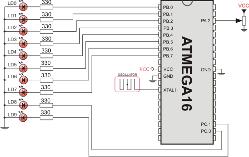
This example code reads analog value from channel 2 and displays it on PORTB and PORTC.
program ADC_on_LEDs;

var adc_rd : word;

begin

  DDRB := 0xFF;               // Set PORTB as output
  DDRC := 0xFF;               // Set PORTC as output

  while (TRUE) do
    begin
      adc_rd := ADC_Read(2);  // get ADC value from 2nd channel
      PORTB := adc_rd;        // display adc_rd[7..0]
      PORTC := Hi(adc_rd);    // display adc_rd[9..8]
    end;
end.
HW Connection

ADC HW connection
What do you think about this topic ? Send us feedback!


