PWM Library
The CCP module is available with a number of PIC32 MCUs. mikroBasic PRO for PIC32 provides a library which simplifies using of the PWM HW Module.
 Important :
PWM module uses either Timer2 or Timer3 module.
Library Routines
PWM_Init
| Prototype |
sub function PWM_Init(dim freq_hz as longword, dim enable_channel_x, timer_prescale, use_timer_x as word) as word |
|---|---|
| Description |
Initializes the PWM module with duty ratio 0. |
| Parameters |
|
| Returns |
|
| Requires |
MCU must have the HW PWM Module. |
| Example |
' Initializes the PWM module at 5KHz, channel 1, no clock prescale, timer2 : dim pwm_period1 as word ... pwm_period1 = PWM_Init(5000, 1, 0, 2) |
| Notes |
Number of available PWM channels depends on MCU. Refer to MCU datasheet for details. |
PWM_Init_Advanced
| Prototype |
sub function PWM_Init_Advanced(dim freq_hz, Fpb_kHz as longword, dim enable_channel_x, timer_prescale, use_timer_x as word) as word |
|---|---|
| Description |
Initializes the PWM module with duty ratio 0. |
| Parameters |
|
| Returns |
|
| Requires |
MCU must have the HW PWM Module. |
| Example |
dim pwm_period1 as word ... pwm_period1 = PWM_Init_Advanced(5000, 50000, 1, 0, 2) |
| Notes |
Number of available PWM channels depends on MCU. Refer to MCU datasheet for details. |
PWM_Set_Duty
| Prototype |
sub procedure PWM_Set_Duty(dim duty, channel as word) |
|---|---|
| Description |
The function changes PWM duty ratio. |
| Parameters |
|
| Returns |
Nothing. |
| Requires |
MCU must have the HW PWM Module. PWM channel must be properly initialized. See PWM_Init routine. |
| Example |
' Set channel 1 duty ratio to 50%: dim pwm_period1 as word ... PWM_Set_Duty(pwm_period1 div 2, 1) |
| Notes |
Number of available PWM channels depends on MCU. Refer to MCU datasheet for details. |
PWM_Start
| Prototype |
sub procedure PWM_Start(dim enable_channel_x as byte) |
|---|---|
| Description |
Starts PWM at requested channel. |
| Parameters |
|
| Returns |
Nothing. |
| Requires |
MCU must have the HW PWM Module. PWM channel must be properly configured. See the PWM_Init and PWM_Set_Duty routines. |
| Example |
' start PWM at channel 1 PWM_Start(1) |
| Notes |
Number of available PWM channels depends on MCU. Refer to MCU datasheet for details. |
PWM_Stop
| Prototype |
sub procedure PWM_Stop(dim disable_channel_x as byte) |
|---|---|
| Description |
Stops PWM at requested channel. |
| Parameters |
|
| Returns |
Nothing. |
| Requires |
MCU must have the HW PWM Module. |
| Example |
' stop PWM at channel 1 PWM_Stop(1) |
| Notes |
Number of available PWM channels depends on MCU. Refer to MCU datasheet for details. |
Library Example
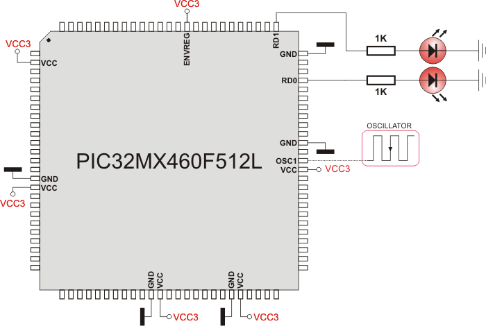
The example changes PWM duty ratio on channels 1 and 2 continuously. If LEDs are connected to channels 1 and 2, a gradual change of emitted light will be noticeable.
program Pwm_Demo
dim current_duty, old_duty, current_duty1, old_duty1 as word
    pwm_period1, pwm_period2 as word

sub procedure InitMain()
  CHECON = 0x32
  AD1PCFG = 0xFFFF                           ' initialize AN pins as digital
  TRISB = 0xFFFF                             ' configure PORTB pins as input
  PORTD = 0                                  ' set PORTD to 0
  TRISD = 0                                  ' designate PORTD pins as output
end sub

main:
  InitMain()
  current_duty  = 100                         ' initial value for current_duty
  current_duty1 = 100                         ' initial value for current_duty1

  pwm_period1 = PWM_Init(5000 , 1, 1, 2)
  pwm_period2 = PWM_Init(10000, 2, 1, 3)

  PWM_Start(1)
  PWM_Start(2)

  PWM_Set_Duty(current_duty,  1)             ' set current duty for PWM1
  PWM_Set_Duty(current_duty1, 2)             ' set current duty for PWM2

  while (TRUE)                               ' endless loop
    if RB0_bit = 1 then                      ' button on RB0 pressed
      Delay_ms(1)
      current_duty = current_duty + 5        ' increment current_duty
      if (current_duty > pwm_period1) then   ' if we increase current_duty greater then possible pwm_period1 value
        current_duty = 0                     ' reset current_duty value to zero
      end if
      PWM_Set_Duty(current_duty,  1)         ' set newly acquired duty ratio
    end if

    if RB1_bit = 1 then                      ' button on RB1 pressed
      Delay_ms(1)
      current_duty = current_duty - 5        ' decrement current_duty
      if (current_duty > pwm_period1) then   ' if we decrease current_duty greater then possible pwm_period1 value (overflow)
        current_duty = pwm_period1           ' set current_duty to max possible value
      end if
      PWM_Set_Duty(current_duty,  1)         ' set newly acquired duty ratio
    end if

    if RB2_bit = 1 then                      ' button on RB2 pressed
      Delay_ms(1)
      current_duty1 = current_duty1 + 5      ' increment current_duty1
      if (current_duty1 > pwm_period2) then  ' if we increase current_duty1 greater then possible pwm_period2 value
        current_duty1 = 0                    ' reset current_duty1 value to zero
      end if
      PWM_Set_Duty(current_duty1,  2)        ' set newly acquired duty ratio
    end if

    if RB3_bit = 1 then                      ' button on RB3 pressed
      Delay_ms(1)
      current_duty1 = current_duty1 - 5      ' decrement current_duty1
      if (current_duty1 > pwm_period2) then  ' if we decrease current_duty1 greater then possible pwm_period1 value (overflow)
        current_duty1 = pwm_period2          ' set current_duty to max possible value
      end if
      PWM_Set_Duty(current_duty1,  2)
    end if

    Delay_ms(1)                              ' slow down change pace a little
  wend
end.
HW Connection

PWM demonstration
What do you think about this topic ? Send us feedback!


