ADC Library
ADC (Analog to Digital Converter) module is available with a number of PIC MCUs. Library function ADC_Read is included to provide you comfortable work with the module.
Library Routines
ADC_Init
| Prototype |
sub procedure ADC_Init() |
|---|---|
| Returns |
Nothing. |
| Description |
Initializes PIC’s internal ADC module to work with RC clock. Clock determines the time period necessary for performing AD conversion (min 12TAD). |
| Requires |
|
| Example |
ADC_Init() ' Initialize ADC module |
ADC_Get_Sample
| Prototype |
sub function ADC_Get_Sample(dim channel as byte) as word |
|---|---|
| Returns |
10 or 12-bit unsigned value read from the specified channel (MCU dependent). |
| Description |
The function aquires analog value from the specified channel. Parameter  Note :
This function doesn't work with the external voltage reference source, only with the internal voltage reference. Note :
This function doesn't work with the external voltage reference source, only with the internal voltage reference.
|
| Requires |
|
| Example |
dim adc_value as word ... adc_value = ADC_Get_Sample(1) ' read analog value from ADC module channel 1 |
ADC_Read
| Prototype |
sub function ADC_Read(dim channel as byte) as word |
|---|---|
| Returns |
10 or 12-bit unsigned value read from the specified channel (MCU dependent). |
| Description |
Initializes PIC’s internal ADC module to work with RC clock and acquires analog value from the specified channel. Clock determines the time period necessary for performing AD conversion (min 12TAD). Parameter  Note :
This function doesn't work with the external voltage reference source, only with the internal voltage reference. Note :
This function doesn't work with the external voltage reference source, only with the internal voltage reference.
|
| Requires |
|
| Example |
dim tmp as word ... tmp = ADC_Read(2) ' Read analog value from channel 2 |
Library Example
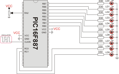
This example code reads analog value from channel 2 and displays it on PORTB and PORTC.
program ADC_on_LEDs
dim temp_res as word

main:
  ANSEL  = 0x04                 ' Configure AN2 pin as analog
  ANSELH = 0                    ' Configure other AN pins as digital I/O
  C1ON_bit = 0                  ' Disable comparators
  C2ON_bit = 0

  TRISA  = 0xFF                 ' PORTA is input
  TRISB  = 0                    ' PORTB is output
  TRISC  = 0                    ' PORTC is output

  while (TRUE)
    temp_res = ADC_Read(2)      ' Get 10-bit results of AD conversion
    PORTB = temp_res            ' Send lower 8 bits to PORTB
    PORTC = word(temp_res >> 8) ' Send 2 most significant bits to RC1, RC0
  wend
end.
HW Connection

ADC HW connection
What do you think about this topic ? Send us feedback!


